
Tail sitters are pretty much the coolest flying machine ever, who wouldn’t want to fly like superman? Exactly, so this is a quick introduction into how to build your very own tail sitting Vertical Take Off and Landing (VTOL) flying machine in small (RC) scale.
The first step is working out what you want to achieve, also known as the requirements. This could include things like speed, how heavy a payload you want to carry and even what colour, automated or flown manually. For me I wanted an aeroplane that would be able to autonomously launch vertically, transition to horizontal flight, then transition back and land on its tail. It needs to be stabilised throughout so even newbies like me could fly it.
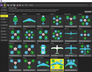
That means it needs an autopilot. I chose Px4 for the autopilot, The software is open source and has a wide range of standard configurations as shown in the figure below. A quick read of PX4 user guide will help save setup time.
There are several hardware options to run the Autopilot software and I chose the Pixfalcon as it is a small form factor autopilot that can be purchased in a kit that includes the GPS and power module. The Pixfalcon is the equivalent to the Pixhawk Mini.
The PX4 quadrotor tail sitter requires a digital airspeed sensor so make sure you add it to the list.
There are a few other parts you will need. So next step is to develop a Parts list (Bill of Materials) to ensure you don’t forget anything and to help build a weight estimate. You need to estimate weight to help size the motors, electronic speed controllers, batteries and ultimately the airframe size.
As a rule of thumb for multirotors, all the motors at full power should produce twice the thrust of your aircraft weight. I used a rough estimate of 1000g for initial sizing and refined from there.
| System / Component | Description | Quantity | Mass (g) | Extended Mass (g) | X location (m) | Moment | |
|---|---|---|---|---|---|---|---|
| Airframe System | I chose a simple off the shelf foam board air frame to reduce build time and to provide enough internal volume for all the components. | ||||||
| Prime Jet Pro Airframe | Assemble airframe, but discard vertical fin, engine mount and do not bond lower fuselage skin. Alternatively build from scratch using plans. If possible choose plans that clearly mark the horizontal flight C of G marked as it saves you having to work it out during flight testing. | 1 | 150 | 150 | 0.43 | 64.5 | |
| Vertical tail | Left and right fins are made from 2 pieces of 3 mm coreflute. Try to replicate the total area of the replaced Prime Jet Pro with most area distributed to the rear. | 2 | 15 | 30 | 0.57 | 17.1 | |
| Motor Mount structure | 6 mm square carbon tube cut into two 200 mm lengths for the left and right structure. | 2 | 6 | 12 | 0.46 | 5.5 | |
| Motor Mount | I used electric motor stand off mounts and carefully drilled the mount to bolt the motor directly to them. After assembly I clamped the mount to the 6mm Carbon tube | 4 | 3.6 | 14.4 | 0.46 | 6.6 | |
| Hardware Various | All joints can be bonded using a hot glue gun. I used velcro to mount electronics, nuts, bolts and cable ties as appropriate. | 8 | 2.5 | 20 | 0.45 | 9.0 | |
| Flight Control system | |||||||
| Control servo | BMS-306DMAX Digital Micro Servo | 2 | 7.1 | 14.2 | 0.49 | 7.0 | |
| Receiver | OrangeRx R617XL cPPM DSM2/DSMX Compatible 6ch Receiver. You can use any receiver that is compatible with your controller. The binding instructions for the manual is incorrect, you need to ground the signal wire, connect power then bind with your transmitter. We found it was easiest to use a 1S battery to apply power and we used the battery balance plug to ground the signal wire. | 1 | 3.5 | 3.5 | 0.63 | 2.2 | |
| Autopilot | PixFalcon Micro PX4. I recommend you install the Autopilot and GPS in the same orientation to simplify autopilot sensor calibration. This is also the most expensive part in the build | 1 | 17 | 17 | 0.33 | 5.5 | |
| GPS & Magnetometer | Ordered as part of the Autopilot kit. | 1 | 20.6 | 20.6 | 0.28 | 5.8 | |
| Power module | Ordered as part of the autopilot kit. I directly soldered the Electronic Speed Controllers (ESCs) to the board. Also you need to solder an additional connector for the Universal Battery Elimination Circuit (UBEC) | 1 | 4.7 | 4.7 | 0.49 | 2.3 | |
| Telemetry | Micro Telemetry Radio Module, remember in Australia use 433 Mhz | 1 | 4.1 | 4.1 | 0.26 | 1.1 | |
| Digital Airspeed Sensor | Pixhawk Digital Airspeed Sensor. The cable is not compatible with the Pixfalcon so you will need to make your own loom. I recommend an inline splice as the connectors are difficult to crimp. The kit comes with the pitot tube. | 1 | 2.8 | 2.8 | 0.26 | 0.7 | |
| Pitot Tube | The pitot tube comes with the Airspeed sensor. Make sure you connect it correctly, and ensure you keep it out of the dirt. The pitot tube needs to be as far forward as practical to allow it to be in undisturbed air in forward flight. | 1 | 3.9 | 3.9 | 0.09 | 0.4 | |
| Wiring and breakout board | The autopilot kit came with a main breakout board. Most components came with their own wiring, however I required extension looms for the servos, an extension loom between the power interface module and the autopilot. | 1 | 5 | 5 | 0.45 | 2.3 | |
| Propulsion | I started by sizing my propulsion for a 1 kg tail sitter. You should aim for the maximum thrust per motor x number of motors = 2 x mass of tailsitter. I chose a motor manufacturer that provided propeller and battery test data on their website to simplify selection. | ||||||
| Electric Motors | DYS SE1806-2550kv Race Edition Brushless Motor 3~4S (CW), and DYS SE1806-2550kv Race Edition Brushless Motor 3~4S (CCW) You can use a common motor for both rotations however the left and right thread self tightens the propeller nut. | 4 | 25 | 100 | 0.45 | 45 | |
| Electronic speed control | Turnigy Multistar 20A ESC With BLHeli OPTO 2-6S. Make sure you size the ESC based on the maximum current draw of the motor and the intended battery voltage. Don’t forget to calibrate your ESCs, you can download the BLheli software and calibrate each one. The easiest approach is through the Autopilot software QGroundControl. | 4 | 18 | 72 | 0.49 | 34.9 | |
| Propellor CW & CCW | Gemfan Propeller 5×3 Yellow (CW/CCW). I picked one that was in the approximate range of what I needed, we also had a lot of spares in the workshop. | 4 | 1.6 | 6.4 | 0.43 | 2.8 | |
| Energy Storage | |||||||
| Battery | Turnigy nano-tech 1300mAh 3S 45~90C Lipo Pack. The important selection criteria for the battery is the voltage, capacity and discharge rate. The voltage is defined by the S rating, S is the number of cells in series, 1S = 3.7 volts for Lipo, 2S = 7.4 and 3S = 11.1. Check your motor specifications to ensure you have sufficient voltage. Capacity is often a case as carrying as much as you can, however if you need to calculate eCalc is a good tool, or calculate from first principles. | 1 | 113.9 | 113.9 | 0.38 | 43.3 | |
| Universal Battery Elimination Circuit (UBEC) | Turnigy 3A UBEC . You need a UBEC to prevent brownout of the Autopilot during heavy manoeuvring. Brownout is when the servos require large current to respond to a control output and it may cause a slight dip in voltage that causes the Autopilot to drop out. The UBEC provides a regulated power supply that reduces battery voltage to the servo voltage. A good description can be found here. | 1 | 11.9 | 11.9 | 0.47 | 5.6 | |
| Totals & Longitudinal C of G (C of G Datum is 0.45 m in forward of the main spar front edge) | Mass (g) | 616 | C of G | 0.43 |
Once you have all the parts it is best to wire all the electrical components and get them functioning. Make sure you read the relevant sections of the Px4 developers guide as a start.You will need a soldering iron and a few additional connectors.
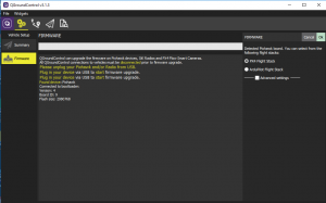
Download QGroundControl, connect your autopilot with the supplied USB cable to download the autopilot firmware. You need to go to Comm Links and add to start. Go to the settings menu, select firmware Ensure you select PX4 Flight stack. If you feel adventurous you can select the advanced settings and choose a beta or developer build. There are many online tutorials search so please watch at least one before you start, as there are many time saving tricks worth learning.
Whilst in QGroundControl go to Airframe and select the VTOL Quad Plane
Assembly
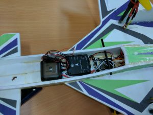
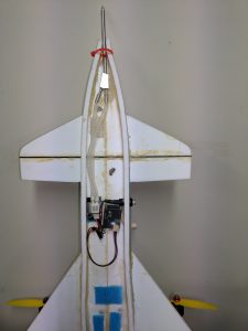
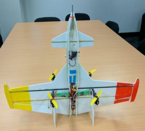
Here are a few pictures of the assembled tailsitter – Underside without battery
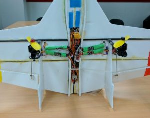
Closeup of power module with Electronic speed controllers
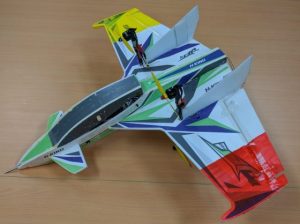
Finished craft – Note the red and yellow wing tips to make flight test a little easier.
Servo Wiring and Mixer File
During the build and test I found an error in the Mixer file, so for new and unusual configurations check the mixer file as they may have undocumented tricks or errors. Fortunately the mixer files are relatively easy to interpret and fix.
This is the Mixer file in the standard firmware. The development guide provides a detailed description of the structure and layout of the mixer file. The layout of mixer files is also described in “Adding a new airframe configuration”.
Interpreting this file is as follows:
R: defines the multirotor configuration, in this case it is an X configuration with 4 motors and 100% authority. So output channels 1-4 are for motors 1 -4
R: <geometry> <roll scale> <pitch scale> <yaw scale> <deadband>
Z:defines a null output, this means output channel 5 is unused in this mixer file.
The left and right elevon mixer files are in the following format:
M: <control count>

O: <-ve scale> <+ve scale> <offset> <lower limit> <upper limit>
S: <group> <index> <-ve scale> <+ve scale> <offset> <lower limit> <upper limit>
S: <group> <index> <-ve scale> <+ve scale> <offset> <lower limit> <upper limit>
So channels 6 and 7 are elevons with Chanel 8 an elevator or canard.
If you want to change the mixer file the simplest is to make the changes and save to the removable SD card in the autopilot.
First step is download the mixer file from the source code collection. Next make a file path on your SD card\etc\mixers
Change the Mixer file as required, I removed the null Z:
You will need a text editor that allows you to save with a Unix End Of File format. I use Notepad ++.
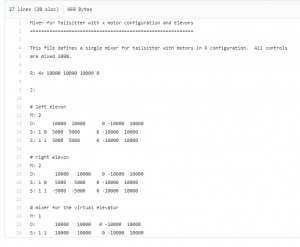
My edited mixer file is as follows:
Mixer for Tailsitter with x motor configuration and elevons
===========================================================
This file defines a single mixer for tailsitter with motors in X configuration. All controls
are mixed 100%.
R: 4x 10000 10000 10000 0
# left elevon
M: 2
O: 10000 10000 0 -10000 10000
S: 1 0 5000 5000 0 -10000 10000
S: 1 1 5000 5000 0 -10000 10000
# right elevon
M: 2
O: 10000 10000 0 -10000 10000
S: 1 0 5000 5000 0 -10000 10000
S: 1 1 -5000 -5000 0 -10000 10000
# mixer for the virtual elevator
M: 1
O: 10000 10000 0 -10000 10000
S: 1 1 10000 10000 0 -10000 10000
Save it onto the SD card and you are ready to test.


